Unlock Superior Casting Solutions
Unlock Superior Casting Solutions
Settings
Settings
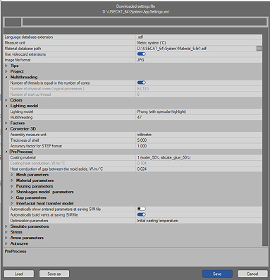
The Settings module is used to customize USECAT to the user needs and configuration.
Main window contains the initial and technological parameters available in the system for assignment of default values. These values will be automatically read by all package modules.
Each string in this window consists of two parts: parameter name and the set value of parameter. In order to change the value of parameter or to browse the list of acceptable values – highlight the string with parameter and click the left mouse button on the right side of the string. The drop-down list of available values will appear. Select the necessary one.
Converter 3D
Converter 3D
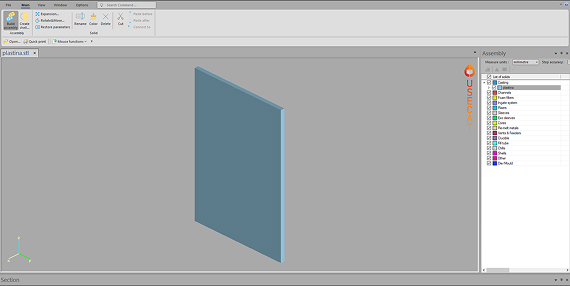
It is the interface module with majority of modern CAD systems. It reads files of STL, STEP and IGS formats and builds inner CVG format of software for performing casting simulation. The following functions are available in the module: Boolean operations (joining, cutting-out), Homothety, shells may be built up and added, geometry may be updated.
One may perform re-triangulation of surface of geometry model.
One may change positions of solids in the model and orientation of the model in space.
PreProcess
PreProcess
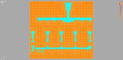
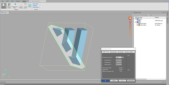
Files converted in the Converter 3D are to be loaded using the PreProcess module and prepared for simulation. Initial and technological parameters for simulation are set here. Firstly mesh is imposed on the casting.
There are possibilities to change calculation domain, cut part of the casting in any of the three main directions, set a symmetry plane, set boundary conditions on the box boundaries. One can look through thermophysical properties of materials available in the Database. An important moment is assignment of proper materials for simulation with initial temperatures for each one.
Solid
Solid
Solidification simulation starts with a full mould of metal. Simulation takes into account both the gravitation and phase conversions. Make sure the casting is oriented in the same position as it is to be cast.
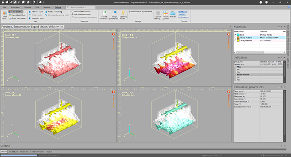
Flow&Solid
Flow&Solid
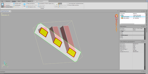
Numerical simulation, with the advantages of low cost, rapid execution, and visualized results, is an important method to study and optimize any casting process. The influence of casting parameters on flow field and temperature field is visualized in detail.
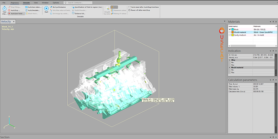
Firstly the mold filling with melt is simulated with taking the heat flux in the metal and in the mould during filling into account. This simulation provides numerous valuable information on filling behavior, temperature field, velocity field, potential cold-flow points and so on. Afterwards solidification of melt in the casting cavity is simulated.
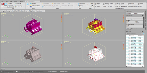
The lagest set of calculated fields is in the Flow&Solid module. Calculated files can be browsed later on in the View module or printed if necessary.
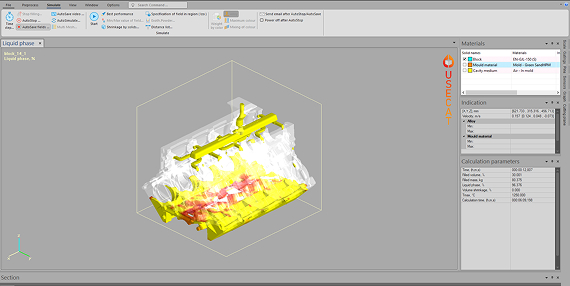
Flow
Flow
Flow is a more advanced mould filling simulation that includes the heat flux both in the metal and in the mould during filling. The simulation stops when the mould is completely filled.
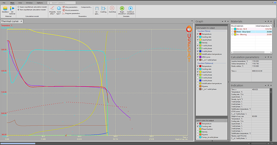
Calibrate
Calibrate
The Thermal Calibration module allows to make solidification calculation of solid with specified shape. As the first step an alloy and mold material are assigned to selected solid, then select the crystallization model (quasi-equilibrium or non-equilibrium). As the result of simulation the cooling curve is received. The calculated cooling curve is compared with the cooling curve obtained from the experiment (for example ATAS curve). Changing thermophysical parameters of alloy and mold material allows to reach better compliance of calculated curve to the experimental one. Then such thermophysical data may ensure more accurate simulations with the real castings.
Flow&Solid is designed to model the fluid flow during mould filling and the solidification process. However, a true top down simulation model would be extremely complex and would require a lot of thermal and flow data that simply are not available. The model in our system is based on phenomenological theory for fluid flow and solidification. Still it is a simplification of reality.
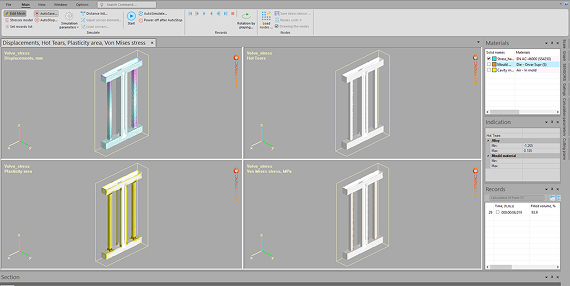
Stress
Stress
The Stress module calculates characteristics of the mechanical state of the casting, mold and casting equipment at the mold filling with melt, solidification of melt and further cooling of the casting, mold and equipment.
The calculation takes into account the solidification process of the melt, the plastic properties of the casting and mold materials, the contact interaction between the casting and mold, as well as the contact interaction of the mold elements with each other.
The results of calculation are the fields of the displacement vector, stress tensor, plastic strain tensor, work of plastic deformation, hot crack formation criterion. Calculated fields are the basis for analyzing the occurrence of cracks and distortion of the casting mold.
Quick
Quick
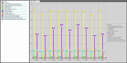
This module is designed as a practical tool for analyses only how the mould filling occurs. The influence of heat flow on the mould is not taken into account in this simulation. The flow simulation allows to study consequences of different gating system designs and the filling sequence in the casting cavity. Such possibility of simulating mould filling often reveals what really happens and gives new knowledge about the pouring process. Many casting defects originates from the bad gating design. Using this module is recommended in order to do a quick study. It is also a good method if the pouring time is very short or if the castings have very heavy sections; then the influence of heat flux into the mould can be disregarded.
Viewer
Viewer
The Viewer module enables studying the descriptor files for various castings. If the casting has been simulated and the snap-shots of simulation were stored, these simulation snap-shots can be scrolled, animated and an AVI movie created. Also the 2D sections of calculated and saved into descriptor 3D fields can be written for further browsing and printing. Most functions from the Simulation module are also implemented in the View module. Additionally there is a possibility to measure distances between different points in the casting, to save 3D defects as STL file, to set additional sensors and to display plots with changes with time of all calculated fields during the casting process. Also comparison of different descriptors is available.
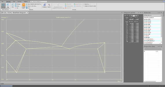
Database
Database
Casting process simulation using CAE software allows to improve quality of cast machine parts by predicting the technological defects inside the cast parts. But casting simulation requires high-quality information concerning thermo-physical and physical properties during solidification.
First of all, thermo-physical properties of alloys during solidification, specific heat capacity and the thermal conductivity, are critical data for successful work of the software solver.
In addition to the properties of cast alloys, it is also necessary to know the exact properties of the molding materials.
The Database module serves to specify the different materials in the casting layout. It allows browsing and updating the thermophysical properties of alloys and mould materials. As default the Database contains the most common alloys and mold materials on the market, designing new materials is also possible.